3D modeling bridges imagination and reality through mathematical precision and creative vision. From organic sculptures to mechanical assemblies, digital geometry is the foundation of modern design and manufacturing.
Ivan Sutherland's Sketchpad revolutionized human-computer interaction, introducing the first graphical user interface for technical drawing. Early CAD systems like CADAM and Unigraphics emerged, transforming engineering workflows from drafting tables to computer terminals.
Pro/ENGINEER introduced parametric modeling, allowing designs to be defined by mathematical relationships and constraints. This paradigm shift enabled rapid design iterations and intelligent assemblies that could adapt to engineering changes.
NURBS-based tools like Rhino brought sculptural freedom to digital design. SolidWorks made parametric CAD accessible to smaller businesses. The rise of polygonal modeling for entertainment and visualization created parallel workflows optimized for different industries.
Cloud-based platforms like Fusion 360 integrate CAD, CAM, and simulation in unified environments. AI-powered generative design explores thousands of solutions based on constraints and objectives, revealing forms that human designers might never imagine.
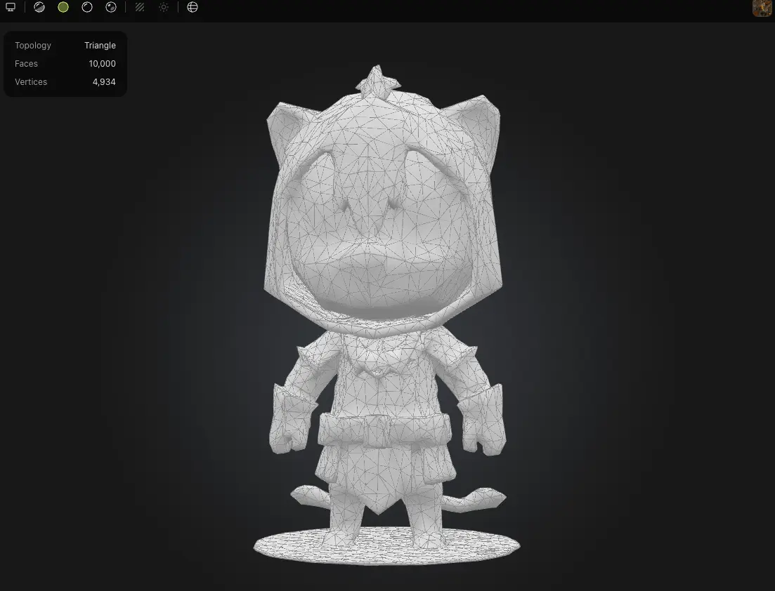
The foundation of game assets, visual effects, and 3D printing. Polygonal models consist of vertices, edges, and faces that define surface geometry through discrete mesh topology.
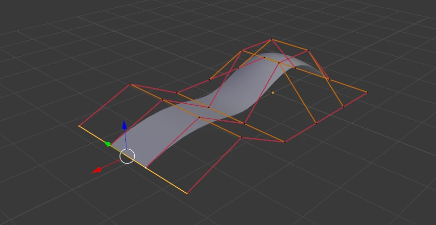
Non-Uniform Rational B-Splines represent curves and surfaces mathematically, enabling infinite resolution and precise control over curvature. Essential for automotive, aerospace, and industrial design.
Feature-based approach where dimensions and relationships define geometry. Changes propagate through the design tree, maintaining intent and engineering constraints throughout iterations.
| Software | Modeling Type | Industry Focus | Learning Curve | Ecosystem | Pricing Model |
|---|---|---|---|---|---|
| Fusion 360 | Parametric + Mesh | Product design, CAM | Moderate | Integrated CAD/CAM/CAE | Subscription |
| SolidWorks | Parametric | Mechanical engineering | Steep | Extensive add-ins | Perpetual license |
| Rhino 3D | NURBS | Industrial design, architecture | Moderate | Grasshopper integration | Perpetual license |
| FreeCAD | Parametric | Open-source projects | Steep | Community workbenches | Free (GPL) |
| Blender | Polygonal + Sculpting | Animation, visualization | Steep | Python scripting | Free (GPL) |
| Onshape | Parametric | Collaborative design | Moderate | Cloud PDM built-in | Subscription |
"The best CAD software is the one your employer uses. But understanding multiple modeling paradigms makes you a more versatile designer. I've seen engineers who mastered NURBS in Rhino bring valuable surfacing insights to SolidWorks workflows."
Standard machining tolerances are ±0.1mm. Tighter tolerances increase cost exponentially. Design parts with appropriate clearances for mating features — typically 0.2mm for sliding fits, 0.05mm for press fits.
CNC mills use rotating tools that cannot create sharp internal corners. Minimum inside corner radius equals tool diameter. Design fillets of at least 1-2mm for 3-axis machining to avoid expensive tool changes or secondary operations.
Thin walls flex during cutting, causing chatter and dimensional errors. Maintain minimum wall thickness of 2-3mm for aluminum, 1.5mm for steel. Consider ribs or gussets for large thin sections to prevent vibration.
3-axis mills have limitations — avoid undercuts unless 5-axis machining is available. Design parts that can be machined from minimal setups. Draft angles help with part ejection and reduce machining time.